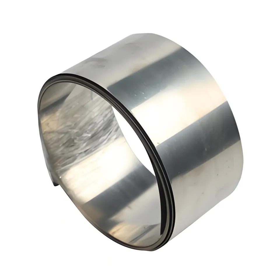
FeCrAl Heating Element Design: Calculating Wire Diameter And Length
Aug 08, 2026

Introduction
Designing a FeCrAl (Iron-Chromium-Aluminum) heating element is one of the most critical engineering tasks in industrial furnace manufacturing. Whether you are building a box furnace, a tubular heater, or a ceramic kiln, selecting the correct wire diameter and length directly determines the element's operating temperature, service life, and energy efficiency. A miscalculation can lead to premature burnout, uneven heat distribution, or even catastrophic failure of the entire heating system.
FeCrAl alloys - such as 0Cr25Al5, 0Cr21Al6Nb, and 0Cr27Al7Mo2 - are the most widely used resistance heating materials in industrial applications worldwide. Their high resistivity, excellent oxidation resistance (forming a protective Al₂O₃ layer), and cost-effectiveness compared to NiCr alloys make them the preferred choice for furnace element design. This guide provides engineers and procurement specialists with the complete calculation methodology for FeCrAl heating element design, including wire diameter, wire length, and surface load optimization.
FeCrAl Alloy Overview
FeCrAl alloys are iron-based resistance heating alloys containing chromium (12-28%) and aluminum (4-7.5%). The aluminum content forms a dense Al₂O₃ oxide layer at high temperatures, providing exceptional oxidation resistance without requiring nickel. The following table compares the five most common FeCrAl grades used in heating element manufacturing:
| Grade | Cr (%) | Al (%) | Max Temp (°C) | Resistivity (μΩ·m) | Density (g/cm³) | Ct at 1000°C |
|---|---|---|---|---|---|---|
| 1Cr13Al4 | 12.0-15.0 | 3.5-5.5 | 950 | 1.25 | 7.40 | 1.12 |
| 0Cr21Al4 | 18.0-21.0 | 3.0-4.0 | 1100 | 1.35 | 7.35 | 1.07 |
| 0Cr25Al5 | 23.0-26.0 | 4.5-6.5 | 1250 | 1.42 | 7.15 | 1.05 |
| 0Cr21Al6Nb | 19.5-22.0 | 5.0-7.0 | 1350 | 1.43 | 7.25 | 1.04 |
| 0Cr27Al7Mo2 | 26.5-27.8 | 6.5-7.5 | 1400 | 1.53 | 7.10 | 1.03 |
Key notes:
- Ct is the resistance temperature correction factor - the ratio of resistance at operating temperature to resistance at 20°C. This must be applied in all design calculations.
- Higher aluminum content increases both maximum temperature and resistivity but reduces ductility at room temperature.
- 0Cr21Al6Nb adds niobium for improved grain structure stability, extending element life at temperatures above 1200°C.
Key Design Parameters and Formulas
Three fundamental parameters govern FeCrAl heating element design: electrical resistance, wire diameter, and surface load. Each must be calculated in sequence.
Step 1: Calculate Required Resistance
Given the supply voltage (V) and desired power (P), the required cold resistance at 20°C is:
R₂₀ = V² / (P × Ct)
Where:
- R₂₀ = Cold resistance at 20°C (Ω)
- V = Supply voltage (V)
- P = Designed power (W)
- Ct = Resistance temperature correction factor at operating temperature
Step 2: Calculate Wire Diameter
The wire diameter is determined by the allowable surface load. Surface load (W) is the power dissipated per unit surface area of the wire, measured in W/cm². If the surface load is too high, the wire overheats and fails prematurely; if too low, the element is unnecessarily long and expensive.
The minimum wire diameter based on maximum allowable surface load is:
d = √(4 × ρ × P² / (π² × V² × W_max))
Where:
- d = Wire diameter (mm)
- ρ = Resistivity of the alloy at 20°C (μΩ·m)
- P = Power (W)
- V = Voltage (V)
- W_max = Maximum allowable surface load (W/cm²)
Step 3: Calculate Wire Length
With diameter determined, the wire length follows from Ohm's law for resistivity:
L = R₂₀ × π × d² / (4 × ρ)
Where:
- L = Wire length (m)
- R₂₀ = Cold resistance (Ω)
- d = Wire diameter (mm)
- ρ = Resistivity (μΩ·m)
Step 4: Verify Surface Load
After calculating diameter and length, verify the actual surface load:
W_actual = P / (π × d × L) (in W/cm²)
Ensure W_actual ≤ W_max for the selected alloy and application type.
Recommended Surface Load Values
The allowable surface load depends on the operating environment, element format, and maximum temperature:
| Application Type | Element Format | Recommended W (W/cm²) |
|---|---|---|
| Open air, ≤1000°C | Spiral/coiled | 1.0 - 1.8 |
| Open air, 1000-1200°C | Spiral/coiled | 0.8 - 1.5 |
| Enclosed (tube), ≤800°C | Straight coil | 3.0 - 6.0 |
| Furnace (radiant), 1200-1400°C | Spiral on support | 1.5 - 3.0 |
| Ceramic-embedded | Flat ribbon | 5.0 - 8.0 |
Worked Calculation Example
Design parameters:
- Power: 3000 W
- Voltage: 220 V
- Alloy: 0Cr25Al5 (max temp 1250°C, ρ = 1.42 μΩ·m, Ct = 1.05 at 1100°C)
- Application: Industrial furnace, spiral element, W_max = 1.5 W/cm²
Step 1 - Cold resistance:
R₂₀ = 220² / (3000 × 1.05) = 48400 / 3150 = 15.37 Ω
Step 2 - Wire diameter:
d = √(4 × 1.42 × 3000² / (π² × 220² × 1.5))
d = √(4 × 1.42 × 9000000 / (9.8696 × 48400 × 1.5))
d = √(51120000 / 715517) = √71.45 ≈ 8.45 mm
Round up to standard wire gauge: 8.5 mm
Step 3 - Wire length:
L = 15.37 × π × 8.5² / (4 × 1.42)
L = 15.37 × 3.1416 × 72.25 / 5.68
L = 3488.7 / 5.68 ≈ 7.48 m (cold state)
Step 4 - Verify surface load:
W_actual = 3000 / (π × 0.85 × 74.8) = 3000 / 199.6 = 15.03 W/cm²
Important: This surface load is for the stretched straight wire. In actual furnace design, the wire is coiled into a spiral, which increases the effective surface load on the coil's outer diameter. The coil pitch ratio (pitch/diameter ratio of 2:1 to 4:1) distributes heat more evenly. The actual design should use the coil's outer surface area for surface load verification. In spiral form, the effective surface load typically drops to 1.2-2.0 W/cm², which falls within the recommended range.
Application Guide
FeCrAl heating elements are used across a wide range of industrial and commercial heating applications. Selecting the correct grade depends on the maximum operating temperature and atmospheric conditions:
- 1Cr13Al4 (950°C max): Household appliances, toaster ovens, hair dryers, low-temperature drying equipment. Most economical FeCrAl grade.
- 0Cr21Al4 (1100°C max): Medium-temperature industrial furnaces, annealing furnaces, baking ovens, infrared heaters.
- 0Cr25Al5 (1250°C max): The most versatile grade for industrial box furnaces, crucible furnaces, ceramic kilns, and heat treatment equipment. Ideal balance of performance and cost.
- 0Cr21Al6Nb (1350°C max): High-temperature furnaces for steel heat treatment, sintering furnaces, and applications requiring extended element life. The niobium addition improves high-temperature structural stability.
- 0Cr27Al7Mo2 (1400°C max): Ultra-high-temperature applications including ceramic sintering kilns, glass melting furnaces, and semiconductor processing. The most premium FeCrAl grade with molybdenum enhancement.
Atmosphere considerations: FeCrAl alloys perform best in oxidizing atmospheres. They are not recommended for reducing or vacuum atmospheres (use NiCr or MoSi₂ instead). In sulfur-containing environments, FeCrAl outperforms NiCr alloys due to the absence of nickel.
FAQ
What is the difference between FeCrAl and NiCr resistance wire for heating elements?
FeCrAl alloys have higher resistivity (1.25-1.53 μΩ·m vs. 1.09-1.18 μΩ·m for NiCr), higher maximum operating temperatures (up to 1400°C vs. 1200°C), lower density (7.1-7.4 g/cm³ vs. 8.3-8.4 g/cm³), and significantly lower cost. However, FeCrAl is more brittle at room temperature and has lower high-temperature strength compared to NiCr. FeCrAl is preferred for industrial furnaces; NiCr is preferred where mechanical flexibility and vibration resistance are critical.
How do I account for the resistance temperature correction factor (Ct) in FeCrAl element design?
The Ct factor represents the ratio of resistance at operating temperature to resistance at 20°C. For FeCrAl alloys, Ct is relatively small (1.03-1.12), meaning resistance changes minimally with temperature. Always divide the hot resistance (R = V²/P) by Ct to obtain the cold resistance for manufacturing. Use the Ct value corresponding to your target operating temperature from the manufacturer's data sheet.
What is the recommended surface load for a FeCrAl spiral heating element in a furnace?
For spiral elements in industrial furnaces operating at 1000-1250°C, the recommended surface load is 1.0-1.8 W/cm² (based on the stretched wire surface). For temperatures above 1250°C, reduce to 0.8-1.5 W/cm². Enclosed tubular elements can handle 3-6 W/cm² due to better heat transfer. Always verify against the manufacturer's maximum surface load rating for the specific alloy grade.
Can FeCrAl heating elements be used in vacuum furnaces?
FeCrAl alloys are not recommended for vacuum or reducing atmospheres. The protective Al₂O₃ oxide layer cannot form or maintain itself without oxygen. In vacuum applications above 1000°C, aluminum evaporates from the alloy surface, causing rapid degradation. For vacuum furnaces, use graphite, MoSi₂, or tungsten heating elements instead.
What wire diameter range is typically available for FeCrAl heating elements?
FeCrAl resistance wire is commonly available in diameters from 0.1 mm to 8.0 mm. For industrial furnace elements, typical wire diameters range from 1.0 mm to 7.0 mm. Wire diameters below 0.3 mm are used for fine appliances and precision heaters. Ribbon (flat wire) formats are also available in widths from 0.5 mm to 30 mm for applications requiring higher surface area.
Conclusion
Proper FeCrAl heating element design requires a systematic approach: select the appropriate alloy grade based on maximum operating temperature, calculate cold resistance from voltage and power, determine wire diameter from surface load constraints, and verify the final design parameters. The formulas and tables provided in this guide enable engineers to perform these calculations with confidence. For high-temperature applications above 1250°C, grades like 0Cr21Al6Nb and 0Cr27Al7Mo2 offer superior performance and longer service life. Always consult your alloy supplier's technical data sheet for grade-specific resistivity and Ct values to ensure design accuracy.